Below you'll find a small collection of photographs of the CRS half
module. Each photo is accompanied by a short description. You can click
on the photo to display a larger version of it.
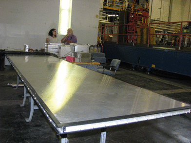
| Whole setup as of August 6. |

|
| Looking into pit. |

|
| New trigger wrapping. |
|
| Group photo 1. |
|
| Group photo 2. |
|
| Looking at the entire setup. |

|
| Looking at the setup from the reflective end of the scintillators. |

|
| The triggers before they were re-wrapped. |

|
| The high voltage box for the triggers. |

|
| The high voltage box for the scintillators. |

|
| Delay boxes. |

|
| Delay boxes. |

|
| Delay boxes connected to scintillators. |

|
| A front view of the coincidence coutnter, discriminator, and amp. |

|
| Meco Mac Computer. |

|
| A front view of the Camac MiniCrate. |

|
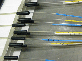
| An end on view of the WLS fibers emerging from the scintillators. You can clearly see the three layers of scintillator. |

|
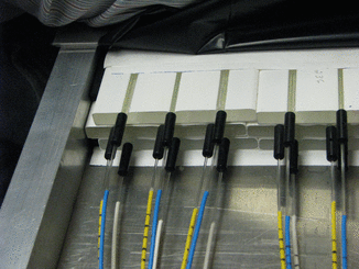
| Another view of the WLS fibers emerging from the scintillators. You can clearly see the three layers of scintillator. |

|
| Another view of the WLS fibers emerging from the scintillators. You can clearly see the three layers of scintillator and also the spacer at the left edge of the top and bottom layer. |

|
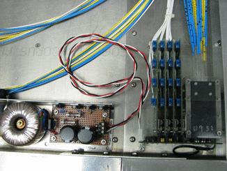
| A top view of (left to right) the power supply, the preamp cards, and the left hand side PMT. |

|
| The DAQ setup at W&M a couple weeks before moving it all to Fermilab. |

|